Abstract
This paper discusses some current challenges limiting the adoption of 3D printed metal parts in numerous industries. I review the development of new approaches, methods and strategies that could enhance existing 3D printing processes for metal components and for the manufacturing industry to fully exploit the advantages of additively manufactured metallic components.
1. Introduction
Metal additive manufacturing (AM) or metal 3D printing has come to be progressively popular recently owing to the numerous advantages [1-3]. Today’s advanced 3D metal printers are capable of producing tooling quality pieces that are functionally comparable to the material properties and qualities required of a final manufactured component [1]. The benefits have attracted interest in high-value industries such as aerospace [4, 5] and in biomedical applications [6].
Just as the multi-axis Computer Numerical Control (CNC) milling machine facilitated the production of high-precision and high-quality components, metal 3D printing is now opening a new frontier of design engineering capabilities.
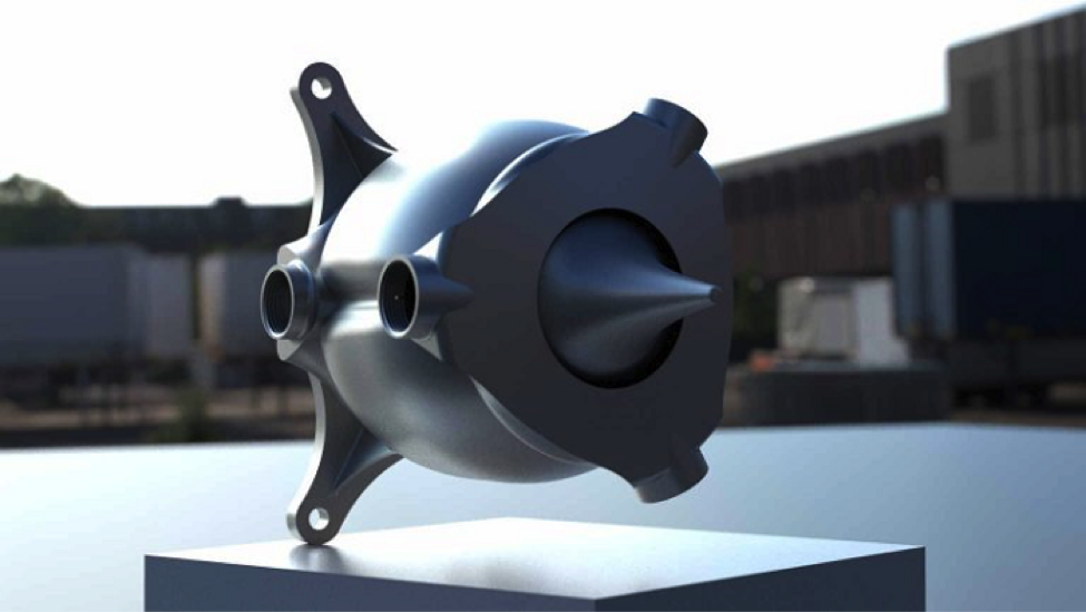
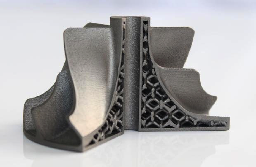
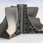
3D printing metal parts allows complex designs with intricate internal structures that were once impossible to be manufactured by traditional machining techniques. Novel complicated designs with hollow internal structures are now possible to be printed with a metal AM system, allowing designers to integrate cooling circulatory systems directly within the structure of the part itself, simplifying manufacturing for high-temperature parts such as gas turbines [7] and rocket engines [8-10].
The ability to design complex internal structures directly into a part allows engineers to reduce the number of individual parts drastically by integrating many components into one printable design. This reduced the overall weight of the 3D printed rocket, which led to substantial improvement in performance and reduced fuel consumption [11].
2. Advantages of AM
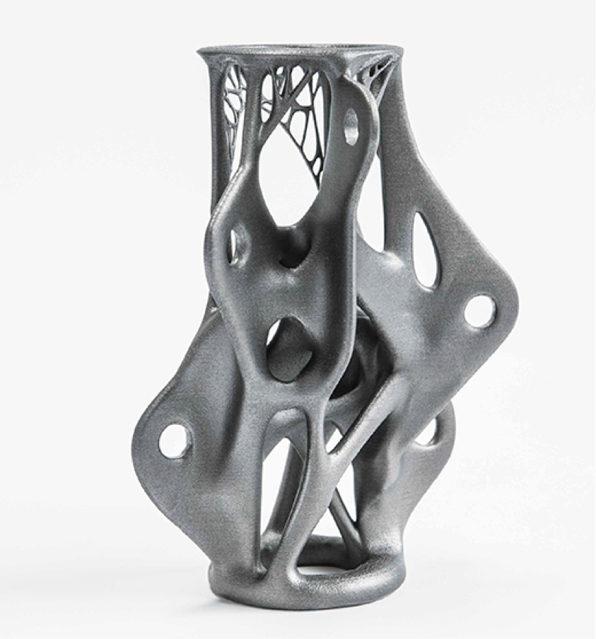
For an engineer to design features in a way that is possible to manufacture and assemble, is a skill that has usually required an understanding of conventional tooling and machining limitations. Poor understanding could lead to a design where mounting holes are inaccessibly located at odd angles which no milling machine can accomplish. A fatal flaw that could prevent that design from being realized.
3D printing eliminates all these design limitations. Much of today’s engineering capabilities are determined by what can be built and 3D printing ushers in new design paradigms once deemed impossible. Complex geometries and labyrinthine channels can be accommodated into a design, and where part counts are reduced by combining features into a single shape that previously required the assembly of several components.
Another immediate benefit that 3D printing provides material savings over traditional machining or casting methods. Engineers can perform topology optimization where finite element analysis is used to predict possible stress locations within a design before it is printed and yet remove unnecessary material within the structure, thus allowing the designer to generate an ideal structure prior to printing [12]. The result is a strong yet lightweight component, a property critical in high-performance motorsports or the aerospace industry. On the note of material savings, it then translates to cost savings as well, conventional methods of machining are known as subtractive manufacturing and is an inefficient method as large portions of the original material are wasted.
In the aerospace industry, where parts are milled down from large blocks of raw metals to a final component – up to 90% of the material is cut away [13]. This waste metric is known as the buy-to-fly ratio in aviation [14], which divides the weight of the final part by the weight of the raw material it was manufactured from [15], and expensive materials such as titanium alloy (Ti6AL4V) used in manufacture could have a ratio as high as 1:22 to 1:33 [16, 17], which means more than 90% of the material is wasted.
This massive source of wastage is a cost that 3D printing immediately reduces, where more than 90% of the material powder constitutes the final component. This weight and material savings are fundamentally valuable to the transportation and aviation industry and translate to fuel savings.
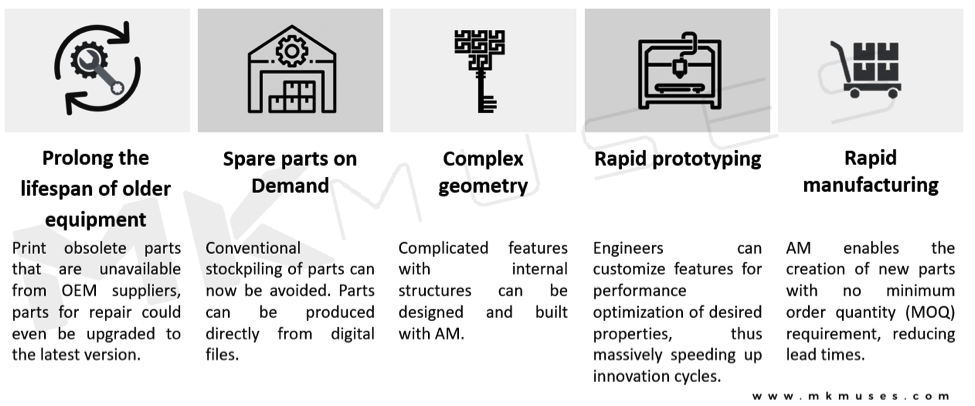
Figure 3 depicts the impact of metal 3D printing to a manufacturing infrastructure. Now managers can reduce spare part inventories, as spare parts can now be produced on demand on-site [18-20], this not only minimizes warehousing and logistics costs, the capability also reduces transportation delays and streamlines the delivery of parts and components to where it is crucially needed.
For many engineers, metal 3D printing is both a boon and bane, there is much hype surrounding the promises that 3D printing claims to bring. However, poor understanding of the capabilities and limitations of metal 3D printing at senior management could generate unrealistic expectations of metal 3D printing. Even with all these amazing applications we rarely see 3D printed parts outside of prototyping applications, it is clear the 3D printing can bring about the next industrial evolution – so what is holding metal 3D printing back from going mainstream?
3. Challenges

To get a better idea of the obstacles preventing metal 3D printing parts from being approved for mass manufacture, we need to understand some fundamental developments achieved in material science today.
Metallurgy and the art of forming of metal parts is a precise process developed over thousands of years of experience beginning from the blacksmiths of the copper age [21, 22], from learning how to change the carbon content during ore smelting to developing forging processes that affect the crystalline structure of the metal, engineers have perfected methods of hot and cold working to effect the desired material properties [21, 23].
Unfortunately, metal 3D printing processes dispense with most of the established forging techniques of metal part manufacture, and engineers must develop new procedures and develop completely novel techniques for studying and optimizing desired 3D printed-derived material properties.
One of the foremost challenges to adoption of 3D printed metal parts is mechanical performance [24]. Strength- and reliability-related concerns become a critical issue with 3D printed parts that are required for load-bearing [25] which is the primary purpose of many metal parts.
Unfortunately, 3D printed metal parts produced today have inferior mechanical characteristics when compared to a traditionally milled or machined component. Metal 3D printing methods today inherently introduce structural defects that include porosities, residual stress, shrinkage cavities, warping, cracking, and often resultant parts have a surface finish and mechanical performance inferior to parts made by machining [26] and is a contributing cause for premature failure.
3.1 Defects
3D printing process-induced defects have been discussed extensively, and these defects cause delamination and fissure formation of the printed part under stress due to weak bonding between layers [27, 28]. One study (see Figure 5) used high-speed synchrotron X-ray imaging and discovered multiple phenomena and molten metal fluid mechanical forces occurring at the melt tracks of the laser-matter boundary.
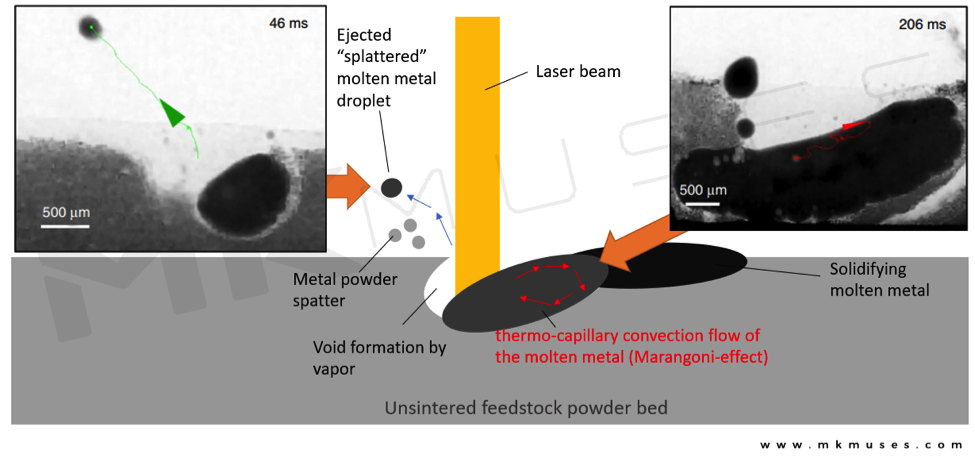
The team found that the laser-matter melting and subsequent solidification of the molten metal experienced thermo-capillary convection, also known as the “Marangoni effect”, and captured splattering of metal droplets and powder particles. As the laser continues its path, the powder in front of it gets blown away by the vapor pressure, which is undesirable, now there is an insufficient metal powder to melt in that region and instead new beads of molten metal forms ahead of the original track deeper into the powder region which eventually coalesces with the original, see a video of it occurring here.
This study also varied several factors like laser speed and laser power to study their effects on the melt tracks properties where they increased the speed of the laser to a point where the metal particles did not have enough time to heat up and coalesce.
These mechanisms and forces have shown to produce pore migration, void formation, and surface imperfections due to splattered droplets dispersing, cooling, and ensuing re-melting by the laser. The physics behind laser-matter solidification has led to a better understanding of why defects form [29].
3.1.1 Porosity
Earlier discussed, pore and void formation can be formed by uneven fluid flow and gas-vapor formation from the laser-matter interaction. Porosity occurs when microscopic cavities form throughout the structure as the part is being printed [30].
Porosity defects can be caused by the AM process itself or from non-homogenous metal powder being used. These voids and pores decrease the general density of the printed part and is a contributing initiator of crack and fatigue stress failures [26].
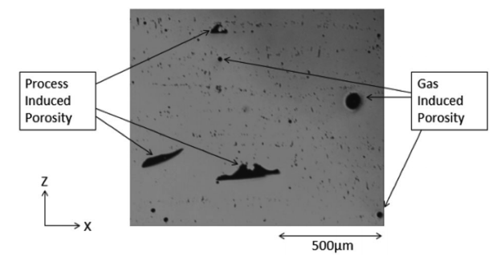
When the metal powder is atomized/sintered by the incoming energy beam, gas pockets can form contained by the metal powder and if there is insufficient laser intensity, the powder particles could fuse unevenly or may not fuse at all.
Pores could also be formed when the powder particles are larger than the layer thickness of the part or if the molten metal fails to flow adequately into the immediate melt region. On the other hand, when the incident laser energy that is too high for the powder material or scan speed, it could cause molten metal droplets to splatter from the laser area, where droplets are ejected from the molten region into surrounding areas, creating a keyhole void [29, 31].
These factors contribute to an imperfect lack of fusion of the metal powder, and under microscopic examination, un-melted powder particles can be observed near a void or pore [27].
3.1.2 Residual Stress
3D metal printing is fundamentally an advanced welding process in 3-axis. Throughout the course of the print, innumerable cycles of repeated heating and cooling, expansion, and contraction occur which result in unpredictable temperature gradients and phase structural changes.
Thermal energy from the sintering causes localized expansion and when the melt pool cools and contracts a high level of residual stress remains. Residual stress in a printed part is highest at the interface of the build plate substrate, being more compressive at the center of the part and more tensile at the edge of the print [32]. When residual stress exceeds the tensile strength of the metal material or substrate, cracking, warpage, deformation, and delamination of the part layers can occur.
3.1.3 Delamination, warpage, and oxidation
If residual stress is not addressed adequately and in addition to pore and void defects within the part, delamination of the layers could occur when the print cools which is considered a print failure and it becomes an unusable part [27]. An irreparable loss of time and material especially if the build time was long or if the part is large.
As a print progresses, the build experiences many cycles of thermal stresses, and as soon as thermal stress surpasses the strength of the substrate, warpage could occur. This is mitigated by positioning appropriate anchor supports in the right locations which are challenging to determine for every geometry.
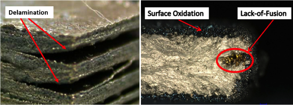
Another issue that could cause cracking and failure is exposure to oxygen and humidity. Ambient factors can cause composition changes in the metal, wherein the instance of titanium alloy (Ti6AL4V), a corresponding increase in oxygen could decrease the content of aluminum.
This is because aluminum has a much lower melting point than titanium, and the energy required to sinter the titanium could potentially vaporize the aluminum and thus altering the composition of the material in the process. To mitigate this issue – an argon-helium environment was developed and reduced oxidation defects at an increased cost of maintaining an inert atmosphere [33].
3.2 Earlier failure
Metal parts are used widely in an industry primarily for their high tensile strength over other material types (e.g. polymers, ceramics). The structural strength of the material is critical to the performance of the machinery (engines, moving parts, fastening bolts, and screws) and premature failure is undesirable – a risk engineers cannot afford to take in high-demand applications.
Fatigue life is a measure of how many cycles of stress loading a part can sustain before failure, because of microstructure crack growth and propagation. When a fatigue crack is formed, each loading cycle will increase the size of the crack, producing striations till the part breaks [21, 23]. The fatigue properties of a material are determined by the amplitude of stress applied cyclically to a sample (S-value) and measuring the number of cycles until failure of the specimen (N-value).
The presence of defects discussed earlier within a printed part could invariably lead to failure from metal fatigue – the weakening of material due to stress, materials could fracture below the maximum strength if the part exposed to cyclic stresses such as vibrations and movement for extended periods and this property is a reason why continued preventive maintenance is always needed for machinery.
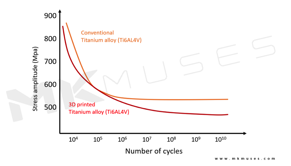
Figure 5 shows an inferior average fatigue strength of an 3D printed titanium component when compared to a traditionally manufactured counterpart. Earlier cyclic failure of the produced part and reduced stresses to failure have been recorded of the printed component [34-37].
Another issue is that different printer systems will also yield parts of different tensile strengths [5], for example in Table 1, we can see that the same design, when produced by different 3D printing systems, exhibit drastically different strength and performance characteristics. This introduces undesirable tolerances that are critical in aerospace or biomedical applications.
| Mechanical Properties | Direct Metal Deposition (DMD) | Laser Metal Deposition (LMD) | Electron Beam melting (EBM) | Direct Metal Laser Sintering (DMLS) |
| Tensile Strength (MPa) | 1.164 + 22 | 1.211 + 31 | 946 | 1.043.3 |
| Yield Strength (MPa) | 1.105 + 19 | 1.100 + 12 | 848 | 797.7 |
The impact that 3D printed parts fail much sooner which is stopping many of the parts from being approved for applications they are best suited for like aviation.
3.3 Post-processing requirements
The science of metal forging is a well-established industrial practice where careful manipulation of a metal’s internal crystalline structure is done to achieve the desired final properties. Traditional techniques of metallurgical manipulation include annealing, tempering, carburizing, case hardening, and quenching.
Typically, when molten metal is cooled, crystals grow at random from specific nucleation sites and form crystal grains, where the size and structure of these grains then account for the metal’s final material properties. Engineers can control the metal’s hardness and ductility by managing heating and cooling profiles in a specific manner [21, 23].
However, 3D printing processes do not follow conventional metallurgical principles, and as discussed earlier, clearly 3D printing processes are much more complicated than just melting some metal powder together and, in the end, the final products that come directly out of a 3D printer are far from finished still need significant post-processing to obtain the desired material properties [38].
To stress-relief and reduce pore cavities, heat treatment is often required and one post-processing technique is a method known as Hot Isostatic Pressing (HIP) where extremely high heat and pressure is applied, removing pores in the printed part [3, 27, 39, 40]. The process increased the tensile strength of the material by up to two times [40-43], with some processed parts showing tensile properties comparable with annealed wrought samples [39].
Unfortunately, this post-processing step inevitably increases the cost and adds to the necessary infrastructure required, reducing the attractiveness of AM applications outside of prototyping.
3.4 Cost
The economic cost is an unavoidable metric for designers and engineers and comparisons with existing processes will be made. The challenge with metal 3D printing today is that printing a part is not scalable, the expense of 3D printing is initially dominated by the capital cost of the printer and the cost per part printed will only marginally trend downwards when more parts are printed due to the long print times required for each part.
Unlike die-casting or mold-forming metal parts, where scaling up production quantities is far more practical. The primary cost commences with the machining of a hard mold needed to form the component, and once that is done, parts can then produce en masse in rapid succession with the intervals of part ejection and cooling before the process is restarted.
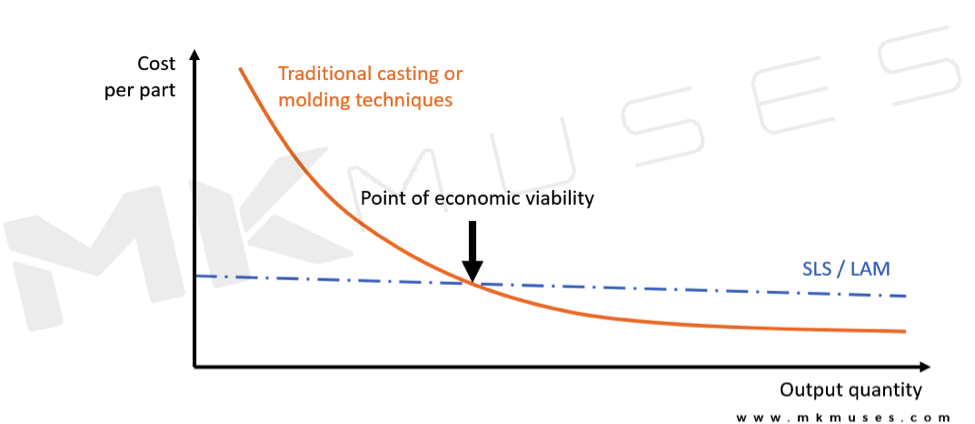
That is unfortunately not the case with 3D printing, Figure 6 shows that costs per part do not decrease significantly regardless of the quantity. This means that it only makes economic sense to utilize 3D printing for complex low-volume production, which is why it is used so frequently in rapid prototyping [44].
On a bright note, just as polymer-extruding Fused Deposition Modeling (FDM) printers have become mainstream amongst hobbyists today, we can soon expect to see metal printers becoming more affordable, largely attributed to expiring patents.
However, it is not just cost preventing 3D printed parts from entering the market, new metal powder materials and improved printing technologies that improve the mechanical performance of 3D printed parts are required to bring 3D printing further mainstream for industrial manufacturing.
4. Recent developments
There are numerous advances in metal 3D printing with new strategies experimented and discussed [46], scientists have found that a gaseous inert environment yielded titanium parts that had superior mechanical characteristics [33], which compliments known titanium forging processes.
The science of metal 3D printing is not a straightforward and simple process as many factors and thermo-kinetic forces influence the outcome of a successful print. To address the problem of porosity forming in a print, engineers must adjust numerous parameters such as laser power, shape, size, and speed of the laser needs to be tuned and modified for specific design geometries – referred to as laser scanning strategy. Engineers have also found that the quality and properties of the powder feedstock are just as important to achieving a quality print.
4.1 Laser scanning strategy
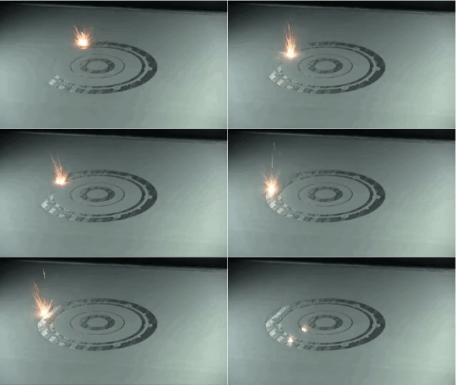
In the pursuit of faster print speeds, numerous studies have shown that faster and higher power lasers do not translate to quality printed parts, instead different scan strategies have been developed with the goal of reducing residual stress, porosity, and to also improve print speeds [27, 30].
The path or route that a laser takes to sinter the metal powder profoundly affects the strength of the final material, this means that how the laser moves have a massive influence on the final mechanical properties of the material [39, 47, 48].

One of the most common laser scan strategies in commercial 3D printers today is the island scan strategy (Figure 11C) where the checkerboard pattern-oriented perpendicular to each other features interspersed opposing scan lines to lower temperature gradients heat distribution [39, 51]. These islands are formed in a random sequence and are created to alleviate residual stresses that form because of uneven heating and cooling within the metal, which can decrease the part’s overall strength.
As a result, numerous other scan strategies such as the helical [30, 49], progressive scan [51], and island contour scan [30, 39, 51] have been investigated to produce a variety of performance outcomes. Another approach developed is the pulsing of the laser to melt the powder gradually, preventing the splattering of molten droplets [46].
4.2 Powder quality
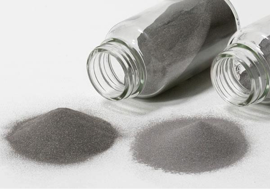
Powder metallurgy has become a critical factor in the outcome of a quality printed part to achieve precise tolerances that are directly dependent on the quality, consistency, size, and shape of the metal powders used [52]. 3D printed parts often have a visible rough surface texture and this can be attributed to the process or the quality of the powder [27].
An ideal powder will exhibit highly consistent size and shape, with tightly controlled particle size distribution and particle size diameters as small as possible is essential for improved flowability on the powder bed. Flowability is essential to ensure a uniform, densely packed layer of powder. The more homogenous a layer is, the denser and less porous the final print will turn out.

However, that is difficult to achieve reliably as the production process enters the realm of nanomaterials. Different atomization techniques result in different morphologies [53]. Additionally, a bigger particle size distribution will allow finer particles to fill gaps between larger particles, resulting in a greater density. Counter-intuitively, this decreases the flowability of the powder [9, 38].
Thus, it is important for engineers to have an adequate understanding of the types of powders available, its characteristics, and performance parameters. This knowledge is vital to selecting the right powder for the right 3D printing process for the appropriate part geometry that is to be printed.
5. Conclusion
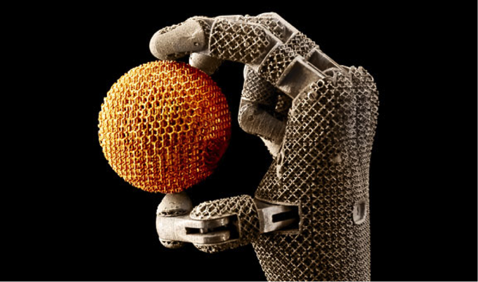
As discussed, there is numerous process knowledge required for avoiding issues and failed prints in metal AM. Different design geometries require different printing parameters and orientation, which often forces engineers and machine technicians to print the same part multiple times to eventually overcome encountered defects.
Even when a print is complete, the part must be post-processed and tested to guarantee it meets quality and performance requirements. A paradigm shift in design for manufacture thinking is required to fully utilize the potential capabilities of 3D printing metal parts.
This is a very new area of research that is ongoing. The metal 3D printing ecosystem is now seeing young engineers beginning their education with this form of design in mind, letting them create designs that were once deemed impossible.
I believe that there is going to be a fascinating fusion of material science and advanced algorithms designed to optimize and improve 3D printed parts where machine-learned AI does the engineering evaluation of the design and determines the appropriate parameters for a successful print. The future landscape of metal 3D printing will be vastly different in the coming years and new developments in this field could one day enable metal 3D printing to complement or replace traditional manufacturing techniques on a larger industrial scale.
6. References
1. Chua, C.K. and K.F. Leong, 3D printing and additive manufacturing. 2014: World Scientific.
2. Frazier, W.E., Metal Additive Manufacturing: A Review. Journal of Materials Engineering and Performance, 2014. 23(6): p. 1917-1928.
3. Zhang, Y., et al., Additive Manufacturing of Metallic Materials: A Review. Journal of Materials Engineering and Performance, 2018. 27(1): p. 1-13.
4. Joshi, S.C. and A.A. Sheikh, 3D printing in aerospace and its long-term sustainability. Virtual and Physical Prototyping, 2015. 10(4): p. 175-185.
5. Lim, C.W.J., et al., An overview of 3-D printing in manufacturing, aerospace, and automotive industries. IEEE Potentials, 2016. 35(4): p. 18-22.
6. Sing, S.L., et al., Laser and electron‐beam powder‐bed additive manufacturing of metallic implants: A review on processes, materials and designs. Journal of Orthopaedic Research, 2016. 34(3): p. 369-385.
7. Sotov, A., et al. Development algorithm of the technological process of manufacturing gas turbine parts by selective laser melting. in IOP Conference Series: Materials Science and Engineering. 2018. IOP Publishing.
8. Werkheiser, N., NASA additive manufacturing overview. 2017.
9. Rawal, S., J. Brantley, and N. Karabudak. Additive manufacturing of Ti-6Al-4V alloy components for spacecraft applications. in 2013 6th International Conference on Recent Advances in Space Technologies (RAST). 2013.
10. Nickels, L., Inside out 3D printing. Metal Powder Report, 2018. 73(3): p. 148-150.
11. Sotov, A.V., et al., Investigation of the IN-738 superalloy microstructure and mechanical properties for the manufacturing of gas turbine engine nozzle guide vane by selective laser melting. The International Journal of Advanced Manufacturing Technology, 2020. 107(5): p. 2525-2535.
12. Langelaar, M., Topology optimization of 3D self-supporting structures for additive manufacturing. Additive Manufacturing, 2016. 12: p. 60-70.
13. Denkena, B., New Production Technologies in Aerospace Industry: Proceedings of the 4th Machining Innovations Conference, Hannover, September 2013. 2013: Springer Science & Business Media.
14. Barnes, J., A. Kingsbury, and E. Bono. Does” low cost” titanium powder yield low cost titanium parts. in PowderMet 2016 international conference on powder metallurgy. Boston. 2016.
15. Ding, D., et al., Adaptive path planning for wire-feed additive manufacturing using medial axis transformation. Journal of Cleaner Production, 2016. 133: p. 942-952.
16. AB, A., Case study: additive manufacturing of aerospace brackets. Advanced Materials & Processes, 2013. 19.
17. Almeida, P. and S. Williams. Innovative process model of Ti–6Al–4V additive layer manufacturing using cold metal transfer (CMT). in Proceedings of the twenty-first annual international solid freeform fabrication symposium, University of Texas at Austin, Austin, TX, USA. 2010.
18. Khajavi, S.H., J. Partanen, and J. Holmström, Additive manufacturing in the spare parts supply chain. Computers in industry, 2014. 65(1): p. 50-63.
19. Li, Y., et al., Additive manufacturing technology in spare parts supply chain: a comparative study. International Journal of Production Research, 2017. 55(5): p. 1498-1515.
20. Liu, P., et al., The impact of additive manufacturing in the aircraft spare parts supply chain: supply chain operation reference (scor) model based analysis. Production Planning & Control, 2014. 25(13-14): p. 1169-1181.
21. Dieter, G.E. and D. Bacon, Mechanical metallurgy. Vol. 3. 1986: McGraw-hill New York.
22. Tylecote, R.F. and R. Tylecote, A history of metallurgy. 1992: Institute of materials London.
23. Smallman, R.E., Modern physical metallurgy. 2016: Elsevier.
24. Palanivel, S., et al., Friction stir additive manufacturing for high structural performance through microstructural control in an Mg based WE43 alloy. Materials & Design (1980-2015), 2015. 65: p. 934-952.
25. Berman, B., 3-D printing: The new industrial revolution. Business horizons, 2012. 55(2): p. 155-162.
26. Castilho, M., et al., Fabrication of computationally designed scaffolds by low temperature 3D printing. Biofabrication, 2013. 5(3): p. 035012.
27. Sames, W.J., et al., The metallurgy and processing science of metal additive manufacturing. International Materials Reviews, 2016. 61(5): p. 315-360.
28. Gong, H., et al., Influence of defects on mechanical properties of Ti–6Al–4 V components produced by selective laser melting and electron beam melting. Materials & Design, 2015. 86: p. 545-554.
29. Leung, C.L.A., et al., In situ X-ray imaging of defect and molten pool dynamics in laser additive manufacturing. Nature Communications, 2018. 9(1): p. 1355.
30. Hagedorn-Hansen, D., et al., The effects of selective laser melting scan strategies on deviation of hybrid parts. South African Journal of Industrial Engineering, 2017. 28(3): p. 200-212.
31. Qiu, C., et al., On the role of melt flow into the surface structure and porosity development during selective laser melting. Acta Materialia, 2015. 96: p. 72-79.
32. Mukherjee, T., W. Zhang, and T. DebRoy, An improved prediction of residual stresses and distortion in additive manufacturing. Computational Materials Science, 2017. 126: p. 360-372.
33. Pauzon, C., et al., Argon-helium mixtures as Laser-Powder Bed Fusion atmospheres: Towards increased build rate of Ti-6Al-4V. Journal of Materials Processing Technology, 2020. 279: p. 116555.
34. Benedetti, M., et al., Fatigue limit of Ti6Al4V alloy produced by Selective Laser Sintering. Procedia Structural Integrity, 2016. 2: p. 3158-3167.
35. Janeček, M., et al., The Very High Cycle Fatigue Behaviour of Ti-6Al-4V Alloy. Acta Physica Polonica, A., 2015. 128(4).
36. Sterling, A., et al., Fatigue behaviour of additively manufactured Ti-6Al-4 V. Procedia Engineering, 2015. 133: p. 576-589.
37. Edwards, P. and M. Ramulu, Fatigue performance evaluation of selective laser melted Ti–6Al–4V. Materials Science and Engineering: A, 2014. 598: p. 327-337.
38. Tian, Y., et al., Influences of processing parameters on surface roughness of Hastelloy X produced by selective laser melting. Additive Manufacturing, 2017. 13: p. 103-112.
39. Qiu, C., N.J.E. Adkins, and M.M. Attallah, Microstructure and tensile properties of selectively laser-melted and of HIPed laser-melted Ti–6Al–4V. Materials Science and Engineering: A, 2013. 578: p. 230-239.
40. Antona, P. and C. Mapelli, Hot Isostatic Pressing (HIP): the State of the Art & Improvement on Two Steels. Metallurgical Science and Tecnology, 2001. 19(2).
41. Wu, M.-W. and P.-H. Lai, The positive effect of hot isostatic pressing on improving the anisotropies of bending and impact properties in selective laser melted Ti-6Al-4V alloy. Materials Science and Engineering: A, 2016. 658: p. 429-438.
42. Popovich, V., et al., Impact of heat treatment on mechanical behaviour of Inconel 718 processed with tailored microstructure by selective laser melting. Materials & Design, 2017. 131: p. 12-22.
43. Sotov, A., et al., Investigation of the Ni-Co-Cr alloy microstructure for the manufacturing of combustion chamber GTE by selective laser melting. The International Journal of Advanced Manufacturing Technology, 2019. 101(9-12): p. 3047-3053.
44. Ruffo, M., C. Tuck, and R. Hague, Cost estimation for rapid manufacturing-laser sintering production for low to medium volumes. Proceedings of the Institution of Mechanical Engineers, Part B: Journal of Engineering Manufacture, 2006. 220(9): p. 1417-1427.
45. Hopkinson, N. and P. Dicknes, Analysis of rapid manufacturing—using layer manufacturing processes for production. Proceedings of the Institution of Mechanical Engineers, Part C: Journal of Mechanical Engineering Science, 2003. 217(1): p. 31-39.
46. Wimpenny, D.I., P.M. Pandey, and L.J. Kumar, Advances in 3D printing & additive manufacturing technologies. 2017: Springer.
47. Wu, A.S., et al., An experimental investigation into additive manufacturing-induced residual stresses in 316L stainless steel. Metallurgical and Materials Transactions A, 2014. 45(13): p. 6260-6270.
48. Gong, H., et al., Analysis of defect generation in Ti–6Al–4V parts made using powder bed fusion additive manufacturing processes. Additive Manufacturing, 2014. 1-4: p. 87-98.
49. Bo, Q., et al., The helix scan strategy applied to the selective laser melting. The International Journal of Advanced Manufacturing Technology, 2012. 63(5-8): p. 631-640.
50. Yuan, P. and D. Gu, Molten pool behaviour and its physical mechanism during selective laser melting of TiC/AlSi10Mg nanocomposites: simulation and experiments. Journal of Physics D: Applied Physics, 2015. 48(3): p. 035303.
51. Carter, L.N., et al., The influence of the laser scan strategy on grain structure and cracking behaviour in SLM powder-bed fabricated nickel superalloy. Journal of Alloys and Compounds, 2014. 615: p. 338-347.
52. DeNigris, J., Taking control of metal powder properties: Exploring the benefits of real-time particle sizing. Metal Powder Report, 2018. 73(4): p. 202-207.
53. McCracken, C.G., C. Motchenbacher, and D.P. Barbis, REVIEW OF TITANIUM-POWDER-PRODUCTION METHODS. international journal of powder metallurgy, 2010. 46(5).





Thanks for introducing a little rationality into this debate. Francene Constantine Severson